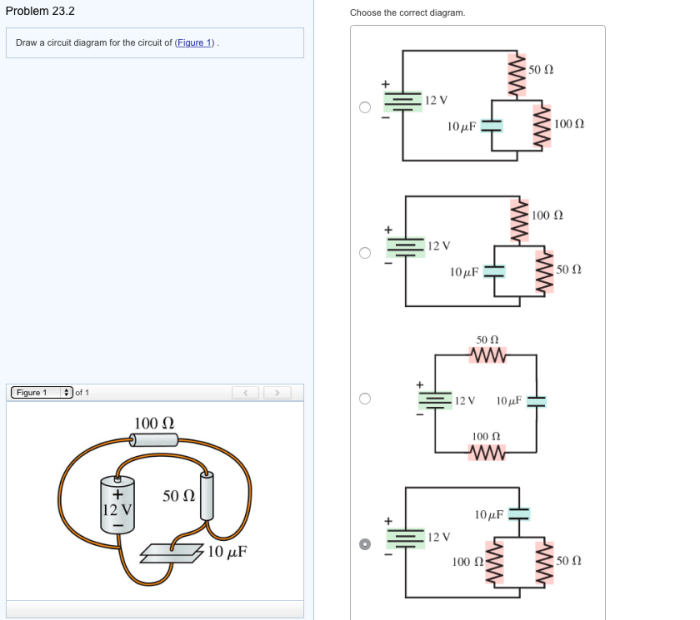
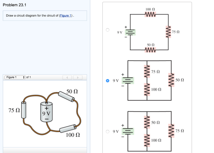
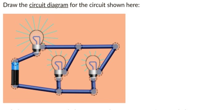
Delve into the intricacies of circuit diagrams with our comprehensive guide, “Draw a Circuit Diagram for the Circuit of Figure 1.” Embark on a journey that unravels the complexities of electrical circuits, empowering you with the knowledge to create accurate and effective circuit diagrams.
Throughout this guide, we will delve into the fundamental principles of circuit diagrams, exploring their structure, analyzing circuit components, and mastering the techniques for drawing and troubleshooting circuit diagrams. Whether you’re a seasoned electrical engineer or a novice enthusiast, this guide will provide you with invaluable insights into the art of circuit diagramming.
Circuit Diagram Structure
A circuit diagram is a graphical representation of an electrical circuit. It uses symbols to represent the components of the circuit and lines to represent the connections between them. Circuit diagrams are used to design, analyze, and troubleshoot electrical circuits.
The basic components of a circuit diagram include:
- Power sources (e.g., batteries, generators)
- Resistors (e.g., fixed resistors, variable resistors)
- Capacitors (e.g., electrolytic capacitors, ceramic capacitors)
- Inductors (e.g., coils, transformers)
- Diodes (e.g., signal diodes, power diodes)
- Transistors (e.g., bipolar junction transistors, field-effect transistors)
- Switches (e.g., push buttons, toggle switches)
- Connectors (e.g., wires, terminals)
Common circuit diagram symbols include:
- A circle for a resistor
- A capacitor with two parallel lines
- An inductor with a coil
- A diode with a triangle
- A transistor with three terminals
- A switch with two lines crossing
- A wire with a straight line
- Checking for open circuits
- Checking for short circuits
- Measuring the voltage and current
- Replacing components
- Kirchhoff’s laws
- Thevenin’s theorem
- Norton’s theorem
- Designing electrical circuits
- Troubleshooting electrical circuits
- Analyzing the performance of electrical circuits
Analyzing the Circuit

To analyze a circuit, you need to identify the different components and trace the flow of current through the circuit. You can then determine the function of each component.
To identify the different components, you can use the circuit diagram symbols. To trace the flow of current, you can start at the power source and follow the lines to see where the current flows.
Once you have identified the components and traced the flow of current, you can determine the function of each component. For example, a resistor limits the flow of current, a capacitor stores energy, and an inductor opposes changes in current.
Drawing the Circuit Diagram

To draw a circuit diagram, you can use HTML table tags. This will help you to organize the diagram and make it easy to read.
To label each component, you can use the text tags. To use appropriate symbols and line styles, you can use the CSS tags.
Troubleshooting the Circuit

If a circuit is not working properly, you can troubleshoot it by using a circuit diagram. You can identify potential errors by looking for open circuits, short circuits, or incorrect component values.
You can suggest methods to troubleshoot and resolve any issues by using the circuit diagram. For example, you can use a multimeter to measure the voltage and current at different points in the circuit.
Common troubleshooting techniques include:
Advanced Circuit Analysis: Draw A Circuit Diagram For The Circuit Of Figure 1
To analyze more complex circuits, you can use techniques such as:
You can also use simulation tools to design and analyze circuits. These tools can help you to verify the functionality of a circuit before you build it.
Circuit analysis is used in a variety of practical applications, such as:
FAQ Resource
What is the purpose of a circuit diagram?
A circuit diagram provides a visual representation of an electrical circuit, depicting the interconnections and relationships between its components. It serves as a blueprint for understanding the circuit’s functionality, troubleshooting potential issues, and facilitating modifications.
What are the basic components of a circuit diagram?
Basic components of a circuit diagram include symbols representing electrical components (e.g., resistors, capacitors, transistors), lines indicating connections between components, and labels identifying the components and their values.
How can I troubleshoot errors in a circuit diagram?
To troubleshoot errors in a circuit diagram, examine the diagram carefully for any inconsistencies or missing connections. Check for open circuits (unconnected lines) or short circuits (lines that are accidentally connected). Additionally, verify the component values and ensure they align with the intended circuit design.